We use cookies and other tracking technologies to improve your browsing experience on our website, to show you personalized content and targeted ads, to analyze our website traffic, and to understand where our visitors are coming from.
⚠️
GDPR & Cookie Policy Notice
In accordance with data protection regulations; the use of mandatory cookies is required for the core functions of our website to operate, ensure data security, and perform analytics. If you reject the use of cookies, it is not possible to benefit from the services on our website due to technical limitations and data synchronization interruptions. You must consent to the use of cookies to access the content on our site.
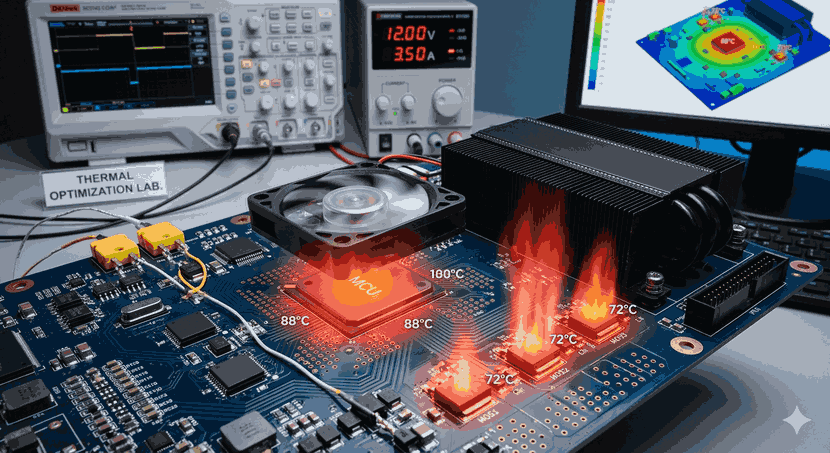
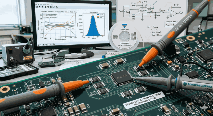
Joule Heating and Advanced Thermal Management Strategies in Modern Electronics
With the miniaturization of electronic systems and the increase in power density, the conversion of energy into heat has become one of the greatest challenges in the engineering world. The resistance encountered when current flows through a conductor causes a portion of the energy to be converted into thermal energy. This phenomenon is called Joule Heating and, if not managed correctly during the system design phase, leads to critical hardware failures, shortened lifespan, and performance losses.
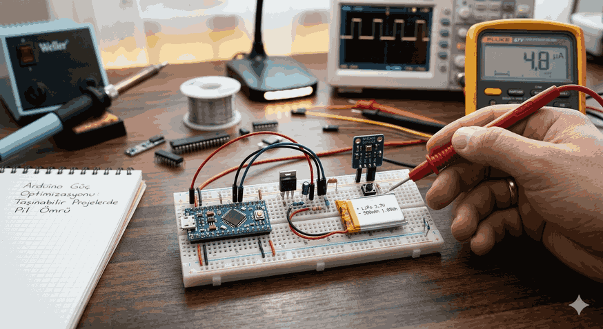
Figure 1: Joule Heating and Advanced Thermal Management Strategies in Modern Electronics.
Physical Mechanism and Mathematical Model of Joule Heating
Joule’s law states that the heat power generated in a conductor is directly proportional to the square of the current passing through it and the resistance of the conductor. Electrical power loss is expressed by the following formula:
$$P = I^2 \cdot R$$
Here, $P$ represents power in watts, $I$ represents current in amperes, and $R$ represents resistance in ohms. However, in real-world scenarios, resistance is not constant; it varies depending on temperature:
$$R(T) = R_0 [1 + \alpha(T - T_0)]$$
In this equation, $\alpha$ is the temperature coefficient. This situation creates a risk of thermal runaway: as temperature increases, resistance increases, and as resistance increases, more heat is generated. Modern circuit designers must use low-resistivity materials and optimized PCB traces to break this cycle.
Thermal Optimization Techniques in PCB Design
Dissipating heat on a printed circuit board (PCB) is not just a matter of physical placement, but also a problem of fluid dynamics and thermodynamics.
Thermal Vias: Copper-plated holes placed under heat-generating components (especially MOSFETs and processors) allow heat to be transferred to inner layers or large copper areas (heat spreaders) on the back surface.
Copper Weight and Trace Width: The width of high-current paths should be calculated according to IPC-2152 standards. Increasing copper thickness (e.g., 2oz/ft² instead of 1oz/ft²) reduces resistance, thereby directly reducing heat generation.
Component Placement: Heat-sensitive components such as capacitors and crystal oscillators should be physically isolated from power stage components.
Advanced Thermal Management: Active and Passive Cooling
Thermal management is the art of moving energy away from a source and dissipating it into the environment.
Passive Management: Heat sinks, thermal interface materials (TIM), and phase change materials are used. The goal here is to minimize the junction-to-ambient thermal resistance ($\theta_{JA}$).
Active Management: Fans, liquid cooling blocks, and Thermoelectric Coolers (TEC/Peltier) come into play. Active cooling is generally managed with PWM (Pulse Width Modulation) controlled loops.
Software Control and Intelligent Thermal Throttling
Hardware-level measures may not always be sufficient. At this point, embedded software (firmware) steps in. Modern microcontrollers and SoCs (System on Chip) protect themselves via internal temperature sensors.
PID Controlled Fan Speed Algorithm
Instead of just running the fan, using a Proportional-Integral-Derivative (PID) controller that adjusts fan speed according to the temperature gradient provides both energy savings and reduced acoustic noise.
Below, a simple thermal control structure and fan speed calculation logic using the C++ language is presented:
#include<iostream>#include<algorithm>classThermalManager {
private:float Kp =2.5f; // Proportional gain
float Ki =0.1f; // Integral gain
float Kd =0.5f; // Derivative gain
float targetTemp;
float integralError =0;
float lastError =0;
public: ThermalManager(float target) : targetTemp(target) {}
// PID control function returning PWM value (0-255)
intcomputeFanSpeed(float currentTemp) {
float error = currentTemp - targetTemp;
if (error <0) return0; // Fan off if below target
integralError += error;
float derivative = error - lastError;
float output = (Kp * error) + (Ki * integralError) + (Kd * derivative);
lastError = error;
// Clamp output to 8-bit PWM limits
int pwmValue = std::clamp(static_cast<int>(output), 0, 255);
return pwmValue;
}
};
intmain() {
ThermalManager coreControl(45.0f); // Target temperature 45 degrees
float currentSystemTemp =58.4f;
int speed = coreControl.computeFanSpeed(currentSystemTemp);
std::cout <<"Required Fan PWM Signal: "<< speed << std::endl;
return0;
}
Software Libraries and Simulation for Power Analysis
During the design phase, finite element analysis (FEA) software plays a critical role in predicting Joule heating. Some basic tools and libraries for electronics engineers are:
OpenFOAM: An open-source CFD library for heat transfer and fluid dynamics.
LTspice / PSpice: Helps determine how much power each component consumes by simulating power dissipation on the circuit.
Python (SciPy/NumPy): Used to model thermal resistance networks and solve time-dependent temperature changes with differential equations.
MLOps and AI-Powered Thermal Prediction
Nowadays, machine learning models are used in high-performance data centers to predict temperature increases caused by Joule heating. A “Digital Twin” is created by collecting sensor data (current, voltage, ambient temperature, workload). Models trained using libraries such as TensorFlow or PyTorch can distribute the workload (task scheduling) to other cores milliseconds before reaching a critical temperature point.
Technical Notes and Critical Warnings
Note 1: Skin Effect
In AC circuits, especially at high frequencies, the current is pushed toward the outer surface of the conductor. This narrows the effective cross-sectional area of the conductor and increases resistance, causing more Joule heating. This must be calculated in RF designs.
Note 2: Thermal Interface Materials (TIM)
The microscopic gaps between a processor and a heat sink are air. The thermal conductivity of air is very low ($\approx 0.026 W/m\cdot K$). Filling these gaps with high-conductivity thermal paste dramatically reduces thermal resistance.
Note 3: Galvanic Corrosion
Using copper and aluminum in the same loop in liquid cooling blocks can lead to metal erosion via electrolysis. This invites leaks and short circuits.
Conclusion and Engineering Perspective
Joule heating is an inevitable result of physics; however, it can be stopped from being an obstacle with the right engineering approaches. Efficient thermal management requires physical improvements at the hardware level and intelligent algorithms at the software level to work in synchronization.
Low-resistance trace designs, advanced PID-controlled cooling systems, and the effective use of simulation tools allow us to push the limits of modern circuits. It should be remembered that the best cooling system is a highly efficient circuit design that ensures heat is never generated in the first place. As efficiency increases in electronics, the amount of waste heat to be managed will decrease, and system stability will reach its peak.