We use cookies and other tracking technologies to improve your browsing experience on our website, to show you personalized content and targeted ads, to analyze our website traffic, and to understand where our visitors are coming from.
⚠️
GDPR & Cookie Policy Notice
In accordance with data protection regulations; the use of mandatory cookies is required for the core functions of our website to operate, ensure data security, and perform analytics. If you reject the use of cookies, it is not possible to benefit from the services on our website due to technical limitations and data synchronization interruptions. You must consent to the use of cookies to access the content on our site.
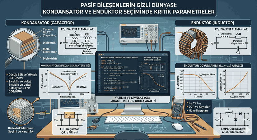
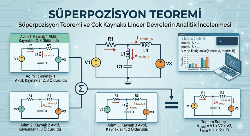
Deep Dive into the Fundamental Building Blocks of Electronic Design: Engineering Foundations of Passive Component Selection
In electronic circuit design, “active” components like microcontrollers, FPGAs, or high-speed processors usually steal the spotlight. However, the stability, signal integrity, and energy efficiency of a system depend heavily on the proper selection of “passive” components: capacitors and inductors.
Figure 1: Deep Dive into the Fundamental Building Blocks of Electronic Design: Engineering Foundations of Passive Component Selection.
The Dynamic World of Capacitors and Non-Ideal Characteristics
Theoretically, a capacitor is merely an element that stores electric charge. However, in a high-frequency circuit or a sensitive analog line, a capacitor is no longer just a $C$ value. A real capacitor is a complex network that is a combination of Equivalent Series Resistance (ESR), Equivalent Series Inductance (ESL), and leakage resistances.
ESR and ESL: Hidden Enemies
One of the most critical parameters in capacitor selection is the ESR (Equivalent Series Resistance) value. Especially in switched-mode power supplies (SMPS), current ripple ($I_{ripple}$) over ESR leads to heat loss according to the formula $P = I^2 \times ESR$. This heat shortens the component’s lifespan while reducing system efficiency.
On the other hand, ESL (Equivalent Series Inductance) limits the performance of the capacitor in high-frequency decoupling applications. After a certain frequency, the capacitor loses its capacitive property and begins to behave inductively. This point is called the Self-Resonant Frequency (SRF).
The heart of a capacitor is its dielectric material. Classifications such as X7R, X5R, and C0G (NP0) used in ceramic capacitors determine the capacitance change with respect to temperature.
C0G (NP0): The temperature coefficient is almost zero. It is indispensable for sensitive filter circuits and RF applications.
X7R/X5R: Offers high capacitance density, but there are significant drops in capacitance value under temperature and applied DC voltage (DC Bias Effect). When you apply half of its nominal voltage to an MLCC capacitor, you can see its capacitance decrease by 20% to 60%.
Inductors: Engineering Limits of the Magnetic Field
Inductors store energy in a magnetic field and resist changes in current. However, saturation and core losses turn inductor selection into an art.
Saturation Current ($I_{sat}$) and Thermal Current ($I_{rms}$)
When selecting an inductor, you see two different current values on the datasheet. $I_{sat}$ indicates the current level at which the inductance value drops from its initial value (typically 20%-30%). If the peak current in your circuit exceeds this value, the inductor reaches “saturation” and becomes no different from a piece of wire, which may cause the circuit to burn. $I_{rms}$ is the continuous current value that increases the component’s temperature by 40°C.
DCR: Direct Current Resistance
DCR, which is the resistance of the winding wire, directly affects power consumption, especially in battery-operated devices. Low DCR is always desired, but this is usually a trade-off that results in larger physical size or lower inductance value.
Software and Simulation: Analyzing Parameters with Code
In modern electronics, component selection does not end with just reading a datasheet. Languages like Python offer powerful tools to analyze complex impedance curves and select the most suitable component. Below is a Python example that models the frequency-dependent impedance change of a capacitor.
Capacitor Impedance Analysis with Python
This script can be used to visualize how parasitic elements (ESR and ESL) distort the ideal behavior of a capacitor. The numpy and matplotlib libraries are standard in such engineering calculations.
The design of filters used at the output of power supplies requires passive components to work in harmonic unison. In an LC filter, the self-resonance frequency of the inductor and the operating range of the capacitor must not overlap.
Q Factor and Damping
In filter circuits, the “Quality Factor” (Q) expresses the ratio of energy storage capacity to energy loss. Filters with very high Q values can cause excessive voltage spikes at the resonance point. At this point, ESR can actually become a “hidden friend” that stabilizes the system (damping effect). Especially in Low Dropout (LDO) regulators, the ESR value of the output capacitor being within a certain range is mandatory for the stability of the control loop.
Engineering Note: Never rely solely on nominal values in your designs. Be sure to include operating temperature, capacitance loss under DC voltage, and aging in your calculations.
Advanced Selection Algorithms and Database Integration
In large-scale production, software approaches are used to select from thousands of different components. In particular, automations that evaluate stock status and technical parameters simultaneously can be developed using the APIs of EDA tools such as KiCad or Altium.
For example, a script that checks the DC Bias loss of all capacitors in a project’s BOM (Bill of Materials) list can prevent future power supply ripples before production.
Example Data Structure and Filtering Logic
A typical data structure used when managing component libraries and a simple Python filtering logic are as follows:
components_db = [
{"part_no": "CAP-001", "val": 10e-6, "type": "X7R", "voltage": 16, "esr": 0.02},
{"part_no": "CAP-002", "val": 10e-6, "type": "C0G", "voltage": 25, "esr": 0.15},
{"part_no": "IND-001", "val": 4.7e-6, "isat": 2.5, "dcr": 0.08}
]
deffind_best_capacitor(target_val, max_esr):
# Find part with target value and low ESR candidates = [p for p in components_db if p.get('val') == target_val and p.get('esr', 1) <= max_esr]
return sorted(candidates, key=lambda x: x['esr'])
selected = find_best_capacitor(10e-6, 0.05)
print(f"Suitable Components: {selected}")
Conclusion: The Unseen Power of Passives
Capacitor and inductor selection may appear to be a simple job of reading tables from a superficial perspective. However, the real power behind high-speed digital systems, sensitive medical devices, and durable industrial controllers is the correct analysis of the physical limits of these passive components.
As a designer; understanding the thermal effect of ESR, the capacitance melting of MLCCs under voltage, the magnetic saturation of inductors, and the dramatic effect of frequency on all these parameters transforms you from an ordinary designer into a master system architect. In the electronics world, “passive” does not mean ineffective; on the contrary, they are the silent cornerstones that keep the system standing.
In your future projects, do not forget to evaluate a component not just by its value, but by all its “hidden” parameters. Modern simulation tools and software-based analyses will be your greatest allies in managing this complex world.