We use cookies and other tracking technologies to improve your browsing experience on our website, to show you personalized content and targeted ads, to analyze our website traffic, and to understand where our visitors are coming from.
⚠️
GDPR & Cookie Policy Notice
In accordance with data protection regulations; the use of mandatory cookies is required for the core functions of our website to operate, ensure data security, and perform analytics. If you reject the use of cookies, it is not possible to benefit from the services on our website due to technical limitations and data synchronization interruptions. You must consent to the use of cookies to access the content on our site.
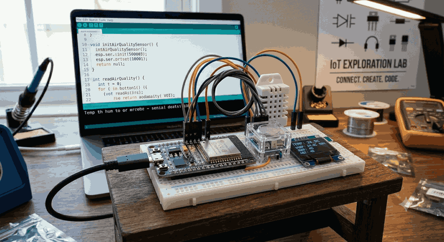
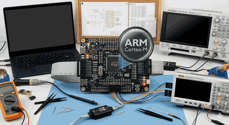
Introduction to the IoT World with ESP32: From Scratch to Advanced Project Development Guide
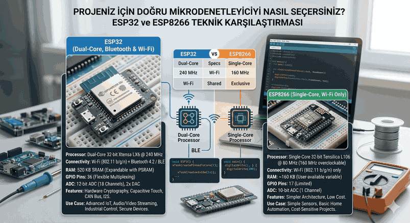
In the Internet of Things (IoT) ecosystem, hardware selection plays a directly decisive role in a project’s sustainability, power consumption, and processing capacity. Developed by Espressif Systems, the ESP8266 and its successor, the ESP32, have revolutionized the embedded systems world by offering low-cost Wi-Fi integration. However, these two platforms represent architectural spectrums that are quite distinct from each other.
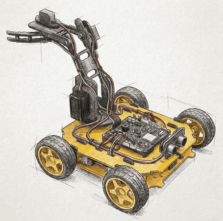
Figure 1: Introduction to the IoT World with ESP32: From Scratch to Advanced Project Development Guide.
Why Choose ESP32 for IoT Projects?
When designing an IoT project, parameters such as processing power, wireless connectivity options, power consumption, and unit cost must be optimized. The ESP32 sits right at the center of this optimization curve.
Differences and Hardware Superiorities Between ESP8266 and ESP32
The ESP8266, the previous darling of the industry, featured only a single-core processor (80 MHz) and a limited number of peripherals. The ESP32 completely revolutionized this architecture, launching with the Xtensa dual-core 32-bit LX6 microprocessor, operating within a frequency range of 160 to 240 MHz.
Processing Power: While the ESP8266 chokes on single-threaded tasks, the ESP32 handles asynchronous operations flawlessly thanks to its dual-core structure. For instance, one core can manage the Wi-Fi stack (TCP/IP) in the background, while the other core processes critical tasks like sensor reading and motor control without latency (under a Real-Time OS).
Connectivity Options: While the ESP8266 only supports Wi-Fi, the ESP32 comes with a combination of both Wi-Fi and Bluetooth (BR/EDR and BLE).
Cost, Dual-Core Performance, and Power Consumption Advantages
Despite its price tag of just a few dollars, the ESP32 competes with many expensive ARM Cortex-M series microcontrollers thanks to its hardware features. With its built-in hardware cryptographic accelerators (AES, SHA-2, RSA, ECC), it can run IoT security standards (such as TLS/SSL) natively without sacrificing system performance. Furthermore, its flexible clock frequency scaling and advanced power modes allow the device to transform from a performance beast into an ultra-low-power tracking device within milliseconds.
ESP32 Hardware Architecture and Pinout
ESP32 development boards (e.g., ESP32 NodeMCU Development Module) typically come in 30 or 38-pin designs. However, designing hardware without errors is impossible without understanding the silicon architecture behind these pins.
GPIO Pins, ADC, DAC, and PWM Usage Rules
The multiplexing capability of the pins on the ESP32 is exceptionally high, meaning almost any GPIO pin can be software-assigned to different functions. However, several critical restrictions apply:
Input-Only Pins: GPIO pins 34, 35, 36, and 39 lack internal pull-up or pull-down resistors and can only be used in input mode (INPUT). They cannot be driven as outputs (PWM or digital logic high).
Strapping Pins: GPIO 0, 2, 5, 12, and 15 determine the boot mode. When permanently connecting external hardware to these pins, care must be taken regarding their logic levels (0 or 1) during startup; otherwise, the board may get stuck in “Flash” mode or enter a boot loop.
ADC Limitations (Analog to Digital Converter): The ESP32 features two 12-bit ADC blocks (ADC1 and ADC2), providing up to 18 channels for analog readings. However, ADC2 channels cannot be used when Wi-Fi is actively running. If you need to read an analog sensor while transmitting data over Wi-Fi, you must use the ADC1 channels (located between GPIO 32 and 39).
DAC (Digital to Analog Converter): There are two 8-bit DAC channels (GPIO 25 and GPIO 26) that provide true analog output.
PWM (LEDC): Hardware PWM channels (16 independent channels) offer flexible frequency and resolution configurations, making them ideal for motor drivers and LED dimmer systems.
Protocol Support: Sensor Interfacing via I2C, SPI, and UART
The ESP32 natively supports multiple serial communication interfaces:
UART: It houses 3 hardware UART units. Serial0 is typically reserved for programming and logging. Serial1 and Serial2 are free to use for external hardware (GPS modules, Nextion displays, etc.).
I2C: GPIO 21 (SDA) and GPIO 22 (SCL) are used by default. It operates stably at 400 kHz (Fast Mode) using the Wire library.
SPI: It provides two usable hardware SPI buses, namely VSPI and HSPI. It can achieve high data rates (up to 80 MHz) for SD card modules and high-resolution TFT displays.
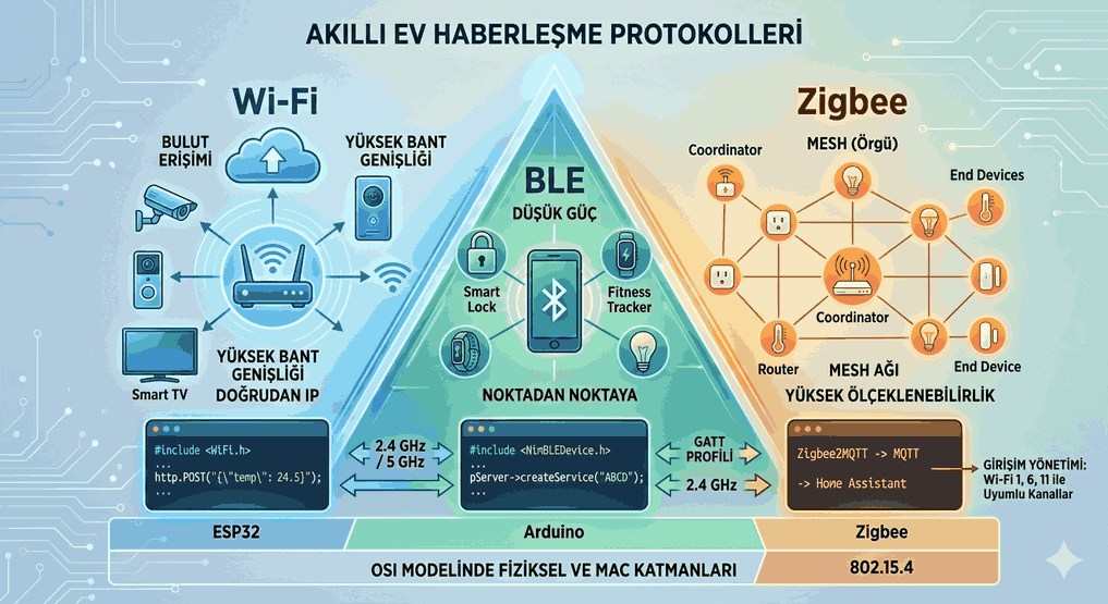
Wireless Connectivity Technologies: Wi-Fi and BLE
The RF (Radio Frequency) subsystem is what makes the ESP32 a true IoT component. Operating on the 2.4 GHz band, this module is optimized for both broadband data transfers and low-energy interactions with nearby devices.
Wi-Fi Station (STA) and Access Point (AP) Modes
The ESP32 can be operated in three different Wi-Fi modes:
Station (STA) Mode: The device connects to a home or office router (modem) as a client, receives an IP address, and accesses the internet.
Access Point (AP) Mode: The device broadcasts its own local Wi-Fi network. Smartphones or computers can connect to this network to access an embedded web server inside the device (this is particularly critical for initial setup and Wi-Fi credential provisioning phases).
Dual (STA+AP) Mode: This is the operational state where both modes are active simultaneously.
Smartphone Integration and Data Exchange with BLE
BLE (Bluetooth Low Energy) is a technology based on the GATT (Generic Attribute Profile) architecture that consumes significantly less energy compared to classic Bluetooth. The ESP32 can be configured as a BLE Server to define services and characteristics. Mobile apps (such as nRF Connect or a custom-built Flutter app) can connect to these characteristics to configure the device wirelessly, independent of an internet connection.
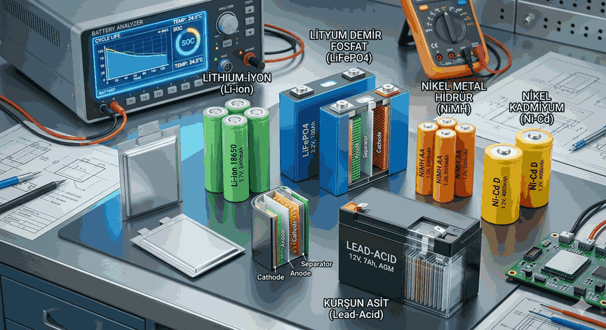
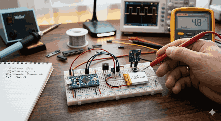
ESP32 Power Management and Deep Sleep Modes
In battery-powered, field-type IoT projects, it is unacceptable for a device to continuously draw 80–120 mA of current. The ESP32 offers advanced power management modes to overcome this challenge.
Secrets to Extending Battery Life in IoT Devices
The ESP32 features Active Mode, Modem Sleep, Light Sleep, and Deep Sleep modes.
Deep Sleep: In this mode, the main CPU cores, Wi-Fi/Bluetooth modules, and almost the entire RAM are powered down. Only the ultra-low-power ULP (Ultra Low Power) co-processor and the RTC (Real-Time Clock) unit remain active. Current consumption drops significantly to the 10 µA to 25 µA range.
Memory Preservation (RTC_DATA_ATTR): When entering deep sleep, standard RAM is wiped. However, variables defined with the RTC_DATA_ATTR attribute are stored in the RTC slow memory. This allows the device to resume right where it left off (retaining counter values, calibration data, etc.) upon waking up.
Waking Up the Device with External Interrupts
The device can be woken up from deep sleep after a pre-determined duration (using a Timer), or via an external physical trigger. For example, when a door sensor (reed switch) is tripped or a button is pressed, the logic change on the respective GPIO pin triggers an external wakeup, returning the device to full performance mode within microseconds.
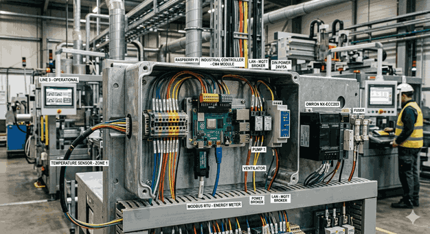
Popular IoT Protocols and ESP32 Integration
Reading data from a sensor is only the first step of the process; moving this data to the cloud requires standardized application protocols.
MQTT Protocol and Broker Connection
MQTT (Message Queuing Telemetry Transport) is a lightweight TCP/IP protocol based on the Publish/Subscribe model, featuring an extremely low packet overhead. It is a perfect fit for IoT systems with constrained bandwidth. The PubSubClient library is frequently used on the ESP32. Data is sent to a broker (Mosquitto, HiveMQ, AWS IoT Core), and any clients (dashboards, databases) subscribed to that topic are updated instantly.
Sending Data to Web Servers via HTTP REST API
For integration with more traditional web infrastructures or third-party enterprise software, HTTP POST/GET requests are utilized. The ESP32 can transmit data in JSON format to RESTful API services using the HTTPClient library. However, the TCP handshake processes and header overheads of the HTTP protocol result in higher energy and data consumption compared to MQTT.
Example Application: Cloud-Connected Sensor Station Project
To materialize this theoretical knowledge, an end-to-end, production-grade C++ source code is provided below. It reads data from a temperature and humidity sensor (DHT22), preserves this data between deep sleep cycles, and securely transmits it to an MQTT Broker over Wi-Fi.
Required Libraries and Software Prerequisites
WiFi.h (Built-in ESP32 Wi-Fi library)
PubSubClient.h (MQTT client developed by Nick O’Leary)
DHT.h (Adafruit Unified Sensor library)
#include<WiFi.h>#include<PubSubClient.h>#include"DHT.h"// --- Hardware and Pin Definitions ---
#define DHTPIN 4 // DHT22 Data pin is connected to GPIO 4
#define DHTTYPE DHT22 // Sensor type: DHT 22 (AM2302)
#define TIME_TO_SLEEP 15 // Duration the device will sleep (in seconds)
#define uS_TO_S_FACTOR 1000000ULL // Conversion factor from microseconds to seconds
// --- Network and Protocol Configuration ---
constchar* ssid ="HIGH_SPEED_WIFI_NETWORK";
constchar* password ="Strong_Wifi_Password_123";
constchar* mqtt_server ="broker.hivemq.com";
constint mqtt_port =1883;
constchar* mqtt_topic ="esp32/sensor_station/data";
// --- Global Object Definitions ---
DHT dht(DHTPIN, DHTTYPE);
WiFiClient espClient;
PubSubClient client(espClient);
// --- RTC Memory Management ---
// This variable survives deep sleep; it is preserved in the RTC memory.
RTC_DATA_ATTR int bootCount =0;
voidsetup_wifi() {
delay(10);
Serial.println();
Serial.print("Connecting to: ");
Serial.println(ssid);
WiFi.mode(WIFI_STA);
WiFi.begin(ssid, password);
int counter =0;
while (WiFi.status() != WL_CONNECTED) {
delay(500);
Serial.print(".");
counter++;
if(counter >20) { // If it fails to connect within 10 seconds, reset or sleep
Serial.println("\nWi-Fi Connection Failed. Entering deep sleep.");
esp_deep_sleep_start();
}
}
Serial.println("");
Serial.println("Wi-Fi connection established.");
Serial.print("IP Address: ");
Serial.println(WiFi.localIP());
}
voidreconnect_mqtt() {
// A single-shot check instead of a blocking loop is critical to prevent getting stuck
if (!client.connected()) {
Serial.print("Attempting MQTT connection...");
// Create a unique Client ID
String clientId ="ESP32Client-";
clientId += String(random(0, 0xffff), HEX);
if (client.connect(clientId.c_str())) {
Serial.println("Connected.");
} else {
Serial.print("Failed, rc=");
Serial.print(client.state());
Serial.println(" Try again in 5 seconds.");
}
}
}
voidsetup() {
Serial.begin(115200);
dht.begin();
// Increment and print boot count
++bootCount;
Serial.println("--- SENSOR STATION ACTIVE ---");
Serial.println("Boot Count: "+ String(bootCount));
// Wi-Fi and MQTT Initializations
setup_wifi();
client.setServer(mqtt_server, mqtt_port);
if (!client.connected()) {
reconnect_mqtt();
}
// Process background MQTT routines
client.loop();
// --- Sensor Reading Phase ---
float humidity = dht.readHumidity();
float temperature = dht.readTemperature();
// Validate the accuracy of readings
if (isnan(humidity) || isnan(temperature)) {
Serial.println("Failed to read from sensor! Data transmission aborted.");
} else {
// Preparing data payload in JSON format
String payload ="{";
payload +="\"boot_count\":"+ String(bootCount) +",";
payload +="\"temperature\":"+ String(temperature, 2) +",";
payload +="\"humidity\":"+ String(humidity, 2);
payload +="}";
Serial.print("Publishing Payload: ");
Serial.println(payload);
// Publish MQTT payload
if(client.publish(mqtt_topic, payload.c_str())) {
Serial.println("Data successfully transmitted to MQTT Broker.");
} else {
Serial.println("Data transmission failed.");
}
}
// Gracefully disconnect MQTT and detach from Wi-Fi network
client.disconnect();
WiFi.disconnect(true);
// --- Deep Sleep Configuration ---
Serial.println("Device entering deep sleep for "+ String(TIME_TO_SLEEP) +" seconds.");
Serial.flush();
// Configure the wakeup timer
esp_sleep_enable_timer_wakeup(TIME_TO_SLEEP * uS_TO_S_FACTOR);
// Initiate deep sleep
esp_deep_sleep_start();
// Code execution stops here. Upon wakeup, the device resets and executes from setup().
}
voidloop() {
// The loop function is left empty when employing a deep sleep architecture.
}
Conclusion and the Role of ESP32 in the Future of IoT
The ESP32 has transformed into an industry-standard development platform thanks to its powerful hardware architecture and rich open-source community support. Its ability to consolidate security (TLS 1.3), stability, and low power consumption into a single SoC (System on Chip) puts it far ahead of its competitors. In the future of Edge AI and smart city infrastructures, ESP32 variants (such as the new generation RISC-V based chips like ESP32-S3 and ESP32-C6) will continue to dominate the ecosystem.